All projects

Hardware · Embedded systems · Power electronics

Phase 2 · commissioning

Smart Energy Node

A four-source DC-microgrid testbed that turns grid-control algorithms into measurable hardware: programmable generation, isolated sensing, dynamic loads and a protected 5.5 V bus, all behind one MQTT interface.
Role
Solo — architecture, firmware & test
Context
Master's project (MP1), HSBI
Supervisor
Prof. Dr. Jörn Loviscach
Focus
Hardware abstraction · HIL
Status
Work in progress · Phase 2
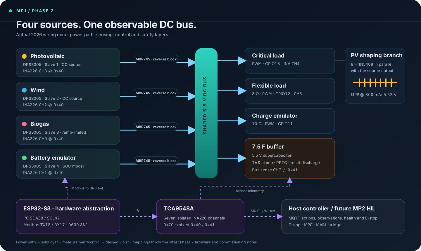
The current Phase 2 architecture. Power flows left to right; the lower layer separates control and measurement. Pin numbers, Modbus slaves and TCA9548A channels match the latest firmware and commissioning notes.
5.5V
nominal shared DC bus and central state variable
4×
independently addressed DPS3005 source channels
7/7
INA226 channels detected in the latest full boot scan
8×
1N5408 diodes selected from measured I–V curves

Purpose

Build the physical layer before trusting the controller.

My companion MP2 project compares multi-agent reinforcement learning with droop and model-predictive control in simulation. MP1 builds the physical target for that work: a small islanded DC grid whose voltage moves with the real balance of source and load current.

The key design choice is a clean hardware-abstraction layer. The host sends normalized actions; the ESP32-S3 translates them into source currents and load PWM, returns measured observations, and enforces safety independently of the controller under test.

Power & measurement path

Every source is commanded, measured and isolated.

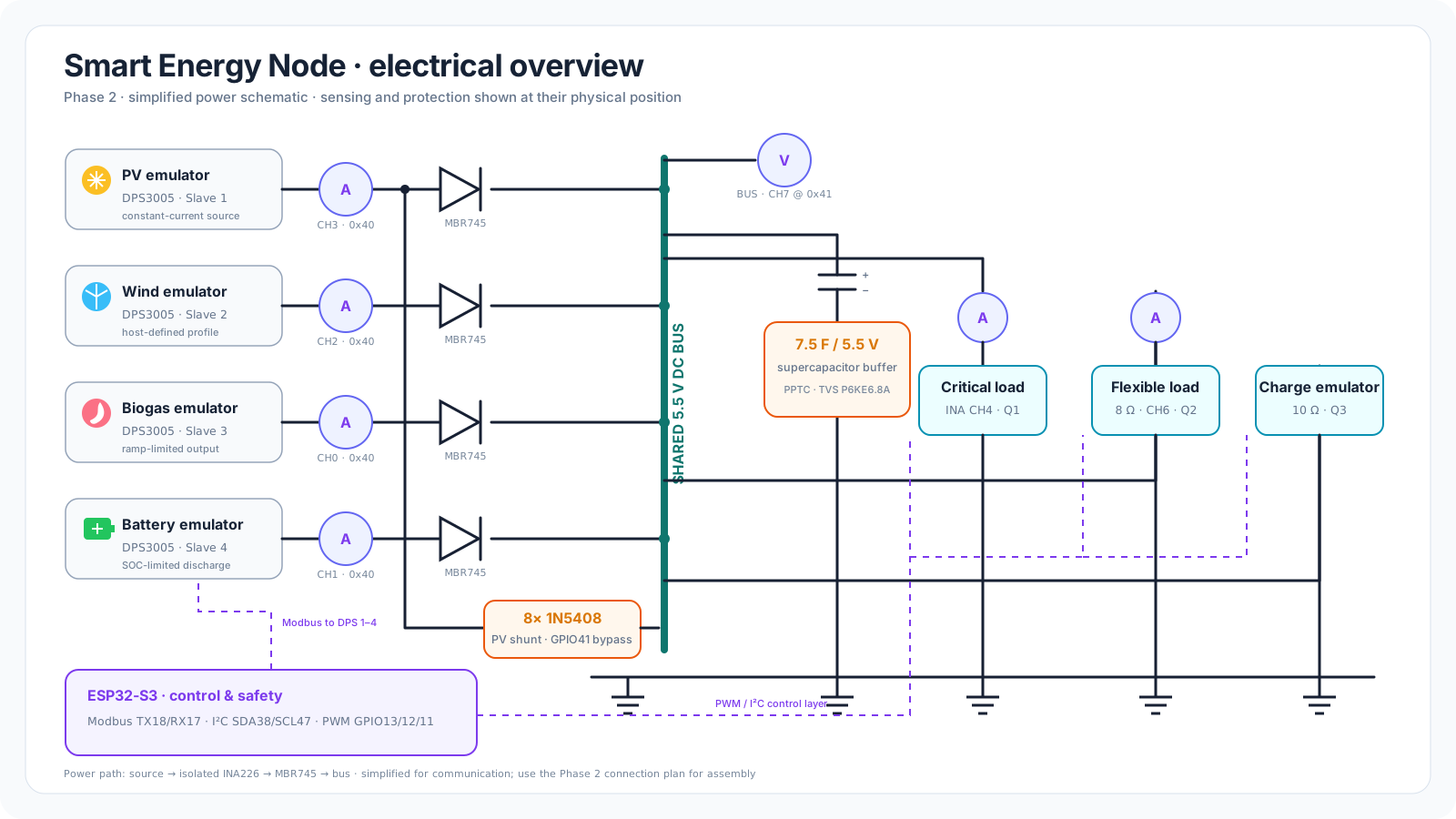
Each source follows the same physical chain: a DPS3005 operates as a programmable CC/CV source, an isolated INA226 measures the actual source current, and an MBR745 Schottky diode blocks reverse current before the channels meet at the bus. A TCA9548A resolves the repeated sensor addresses.

01DPS3005current set-point
02INA226V · I · P measured
03MBR745reverse-current block
045.5 V busshared dynamic state
RoleDPS slaveSensor routeControl behaviour
PV1CH3 @ 0x40passive diode-shunt mode or bypass
Wind2CH2 @ 0x40host-defined source profile
Biogas3CH0 @ 0x40minimum output and ramp limit
Battery4CH1 @ 0x40SOC-dependent charge/discharge limits
Simplified electrical schematic. This restores the circuit-level view of the project and adds the missing 7.5 F / 5.5 V supercapacitor, protection, real Phase 2 sensor routes and the three PWM load branches.

Measured PV emulation

Eight diodes put the MPP where the bus needs it.

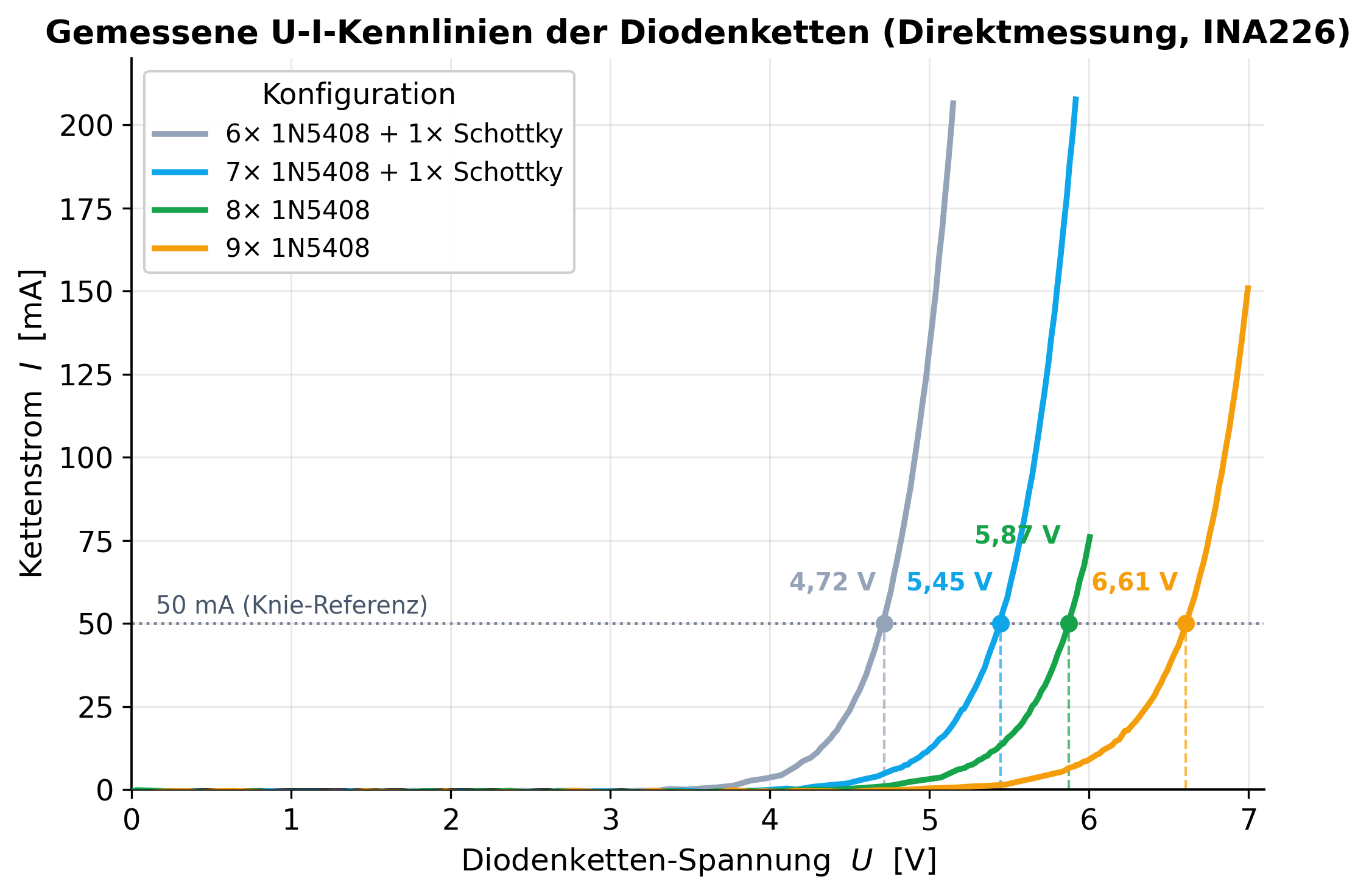
Instead of drawing an ideal PV curve in software, the hardware creates it with a constant-current source and a diode chain connected as a shunt. I swept four physical configurations with an isolated INA226, fitted the exponential branch, and evaluated their maximum-power point over the intended current range.
8× 1N5408 PV emulator — the engineered I–V knee output current (mA) MPP · 5.52 V ≈ 285 current-source region diode shunt 0123455.52 V67 0150300 bus voltage (V)
Why the diode chain creates a knee. Below the knee, almost all source current reaches the bus; above it, the parallel diode chain diverts current sharply. The marker uses the fitted Phase 2 result for 8× 1N5408 at 300 mA; the measured curves follow below.
Direct measurement, not a schematic curve. Four configurations were swept on 18 June 2026. At 50 mA the measured knee moves from 4.72 V to 6.61 V as the chain grows.
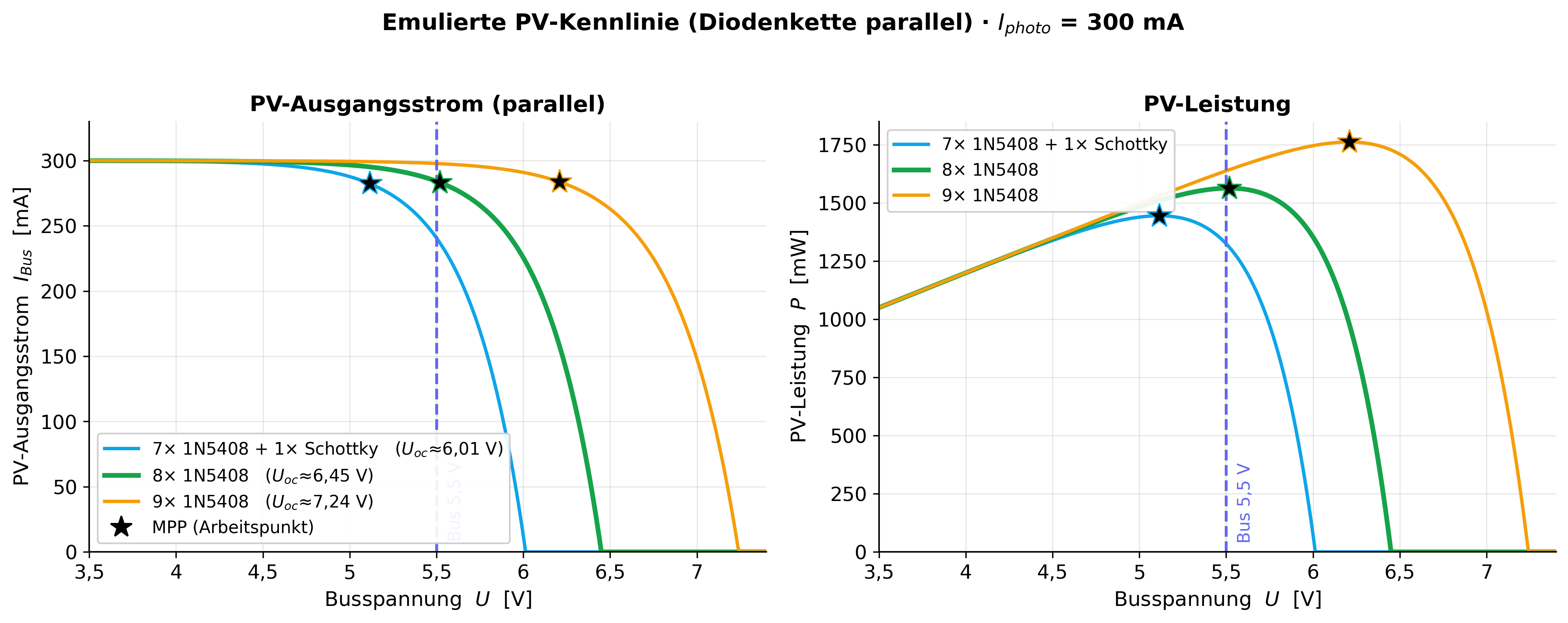
Model derived from the measurements. At 300 mA, 8× 1N5408 places the MPP at 5.52 V. Seven diodes peak too early; nine make the source too stiff.
1N5408

Selected configuration

MPP range 5.2–5.68 V for 100–500 mA, with 84–97% of the source current still delivered to the bus at 5.5 V.

Firmware & safety

A hardware API with its own guardrails.

01

Observe

Seven isolated sensor routes publish bus voltage, source currents, load currents and validity masks over MQTT.

02

Act

Normalized host actions become source-current set-points, PWM load commands and a battery charge/discharge decision.

03

Protect

Overvoltage latching, undervoltage load shedding, current caps, E-stop and a heartbeat watchdog stay in firmware.

04

Reset

A guarded discharge path returns the supercapacitor to a known state before each repeatable experiment.

I²C GPIO38 / GPIO47 · 400 kHz Modbus TX18 / RX17 · 9600 8N1 Loads GPIO13 / 12 / 11 · PWM Host MQTT · actions / observations / health

Commissioning evidence

What Phase 2 proves — and what it does not yet prove.

VerifiedCore paths
  • All seven INA226 positions detected in the full boot scan.
  • TCA9548A channel and mixed-address map implemented in firmware.
  • All four DPS outputs addressed; set voltages matched INA readings within roughly 10 mV in the isolated test.
  • MQTT actions, observations, health telemetry and safe zero-action confirmed.
  • Physical diode-chain sweep and quantitative 8-diode selection completed.
OpenSystem validation
  • Verify the complete four-source power path under load.
  • Pulse-test and calibrate the final load-to-sensor assignments.
  • Replace blocking Modbus writes with a non-blocking state machine.
  • Resolve the missing DPS readback path or keep INA-based confirmation as the authority.
  • Run and evaluate the MP2 controllers on the physical closed loop.

Why this distinction matters. The project has a working measurement and actuation foundation, but it is not presented as a finished HIL benchmark. That boundary is part of the engineering result, not a footnote.

Technology

Toolchain.

ESP32-S3C++ / PlatformIOPower electronicsINA226TCA9548AModbus RTUMQTTPythonPandasMatplotlibHardware-in-the-loop